A Hydraulic System uses a reservoir to store and reserve fluid, allowing the system to operate continuously without the need for constant refilling. The fluid level needs to be within a certain range to ensure that the system's components are properly lubricated, while also preventing the system from overflowing. The reservoir can also act as a pressure accumulator, which allows a system to store energy in the form of fluid pressure, which can be used to power the system when needed. Additionally, it provides a sizable surface area for radiating heat from the hydraulic fluid to the surroundings.
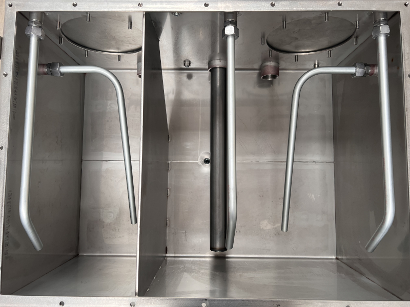
A baffle is used to separate the fluid entering the reservoir from the fluid entering the pump suction line and to slow the liquid down from its high entrance velocity as it enters the reservoir to allow impurities and pollutants/contaminants to settle. To help air bubbles from the fluid be absorbed, there is an air space above the fluid. During periods of peak operation, access to remove used fluid and pollutants from the system during shutdown and a lack of large volumes is intermittently required. As well as a surface for mounting additional system components, if practical.
Gravity drain-back - when working fluid in the system flows back to reservoir or tank due to gravity instead of being circulated by the pump, usually occurs during shutdown or when systems valves are closed.
Reed switch - an electromechanical switch operated by an applied magnetic field.
Deaeration - the removal of air molecules (usually meaning oxygen) from another gas or liquid.
These points cover the conventional functions of reservoirs, but emerging trends might deviate from the pattern.
The size of the reservoir is determined by the fluid volume required to meet the system's needs. The volume required to maintain consistent fluid levels and to compensate for leaks or internal losses are also considered. It is important to have a large enough reservoir to accommodate the fluid volume required for the specific application and to provide enough reserve volume for unexpected events.
In recent times hydraulic systems have required reservoirs that are significantly smaller than those based on conventional examples. Most systems call for some level of special care, so it's crucial to refer to industry standards for minimal requirements.
The reservoir volume is the first and most important variable, even though there are additional factors that need to be discussed. The volume of a hydraulic reservoir should be three to four times the weighted output of the system's fixed displacement pump or the mean flow rate of its variable displacement pump, according to a solid rule of thumb for doing so.
For example, a system with a 5 gallon per minute pump will need a reservoir with a volume of between 15 and 20 gallons. This rule will provide the user with a volume that will allow sufficient time for heat dissipation, contaminant settling, and deaeration to occur between work cycles of the system. However, this rule isn’t universal, its just a good rule of thumb for your average reservoir; due to economic factors such as the need to conserve space, to reduce oil consumption, and to lower system costs, the design goals of today are changing. Therefore, the fluid volume rule won’t be applicable to every system.
Even if you were to follow the general rule of thumb of three to four times pump size, there are additional elements that affect the reservoir size as well. Certain circuit components, like sizable accumulators or cylinders, could use a lot of fluid. Naturally, this would necessitate the specification of a larger reservoir to ensure that the fluid level does not fall below the pump inlet with respect to flow, this could introduce air to the system, which could lead to cavitation.
Systems exposed to high ambient temperatures require a larger reservoir unless they incorporate a heat exchanger. Be sure to consider the substantial heat that can be generated within a hydraulic system. This heat is generated when the hydraulic system produces more power than is consumed by the load. A system operating for significant periods with pressurised fluid passing over a relief valve is a common example.
Reservoir size, therefore, is often determined primarily by the combination of highest fluid temperature and highest ambient temperature. All else being equal, the smaller the temperature difference between the two, the larger the surface area (and, therefore, volume) required to dissipate heat from fluid to the surrounding environment. Of course, if ambient temperature exceeds fluid temperature, a water-cooled or remote-mounted heat exchanger will be needed to cool the fluid. In fact, for applications where space conservation is important, heat exchangers can reduce reservoir size and cost dramatically. Additionally, the reservoir may not be full at all times, so it may not be dissipating heat through its full surface area all of the time.
The reservoir should contain additional space equal to at least 10% of its fluid capacity. This allows for thermal expansion of the fluid and gravity drain-back during shutdown, yet still provides a free fluid surface for deaeration.
A trend toward specifying smaller reservoir has emerged as a means of reaping economic benefits. A smaller reservoir is lighter, more compact, and less expensive to manufacture and maintain than one of traditional size. Moreover, a smaller reservoir reduces the total amount of fluid that can leak from a system which is important from an environmental standpoint.
But specifying a smaller reservoir for a system must be accompanied by modifications that compensate for the lower volume of fluid contained in the reservoir. For example, because a smaller reservoir has less surface area for heat transfer, a heat exchanger may be necessary to maintain fluid temperature within requirements. Also, contaminants will not have as great an opportunity for settling, so high-capacity filters will be required to trap contaminants that would otherwise settle in the sump of the reservoir.
Reservoirs come in many different shapes. The prism with the highest heat-transfer surface per unit volume is a square or rectangular prism. On the other hand, it might be cheaper to build a cylinder. If the reservoir is shallow, wide, and long, it can be occupying more space on the floor than is necessary and not fully utilising the heat-transfer surface of the walls.
The reservoir top has the greatest potential for heat transfer to the atmosphere since hot fluid is less dense than cold fluid and will rise above it, theoretically. Contaminants, however, frequently assemble on the reservoir top in extremely unclean conditions and serve as insulation. Because of this, the reservoir's sides should occasionally be the most efficient place for heat transfer. This limits the effective heat transfer from the reservoir's top. A tall and narrow geometry, on the other hand, preserves floor space and offers a sizable surface area for heat transfer from the sides.
.png)
Perhaps the greatest challenge to using a smaller reservoir lies with removing air from the fluid. A traditional reservoir provides the opportunity for air to escape from fluid before it is drawn into the pump inlet. Providing too small a reservoir could allow aerated fluid to be drawn into the pump. This could cause cavitation and eventual damage or failure of the pump. When specifying a small reservoir, consider installing a flow diffuser which: reduces the velocity of return fluid, helps prevent foaming and agitation and reduces potential pump cavitation from flow disturbances at the inlet. Another technique is to install a screen at an angle in the reservoir. The screen collects small bubbles, which join with others to form large bubbles that readily rise to the fluid's surface.
The best way to prevent aerated fluid from being drawn into the pump, however, is to prevent aeration of fluid in the first place! This can be done by paying careful attention to fluid flow paths, velocities, and pressures when designing the hydraulic system.
Visit this link to learn more about how to calculate these values in a hydraulic system.
The location of the reservoir is also important. It should be easily accessible for maintenance and filling, and should be located in a place that allows for proper ventilation to dissipate the heat generated by the system. It should also be located in a safe location, away from potential hazards.
The location of a hydraulic reservoir is typically determined by several factors, including:
Accessibility - The reservoir should be located in a place that is easily accessible for maintenance and servicing.
Heat dissipation - The reservoir should be located in a place where heat generated by the system can be dissipated effectively.
Space limitations - The reservoir should be located in an area where there is enough space to accommodate its size and shape.
Safety - The reservoir should be located in a place that is safe and away from potential hazards, such as sources of heat or flame.
Gravity flow - The reservoir should be, in most cases, located at a higher point than the other components of the system to allow for gravity flow of the fluid.
Piping routing - The reservoir should be located in a way that makes the routing of pipes and hoses to the other components of the system as simple and straightforward as possible.
Cost - The cost of installing and maintaining the reservoir should be taken into consideration when deciding on its location.
Ultimately, the best location for a hydraulic reservoir will depend on the specific requirements of the system and the environment in which it will be used. An experienced hydraulic engineer will be able to assess the system and make recommendations on the optimal location of the reservoir.
Reservoirs can be constructed from various materials, such as steel, aluminium, and plastic, depending on the application and the fluid being used. Each material has its own advantages and disadvantages, and the choice of material depends on the specific requirements of the application. They can also be designed with features such as sight glasses, fluid level indicators, and breathers to help monitor and maintain the fluid level and quality.
Compatibility - The material should be compatible with the type of fluid being used in the system. Some materials may react with certain fluids, causing damage to the reservoir or the fluid.
Temperature - The material should be able to withstand the temperature range of the fluid and the surrounding environment. Some materials may become brittle or degrade at high temperatures, while others may not be able to withstand low temperatures.
Pressure - The material should be able to withstand the pressure range of the system. Some materials may be more suitable for high-pressure systems, while others may be better suited for low - pressure systems.
Corrosion resistance - The material should be resistant to corrosion from the fluid and the environment. Some materials may be more susceptible to corrosion than others.
Weight - The material should be lightweight enough to be easily transported and installed on site.
Cost - The material should be cost-effective, with a balance between the cost of the material and the cost of the maintenance.
.jpg)
Common materials used to construct hydraulic reservoirs include aluminium, steel, and plastic. Aluminium is lightweight, corrosion-resistant, and has a good strength-to-weight ratio. Steel is strong, durable, and can withstand high pressures and temperatures. Plastic is lightweight, corrosion-resistant, and can be moulded into a variety of shapes, but it is not suitable for high-temperature or high-pressure applications.
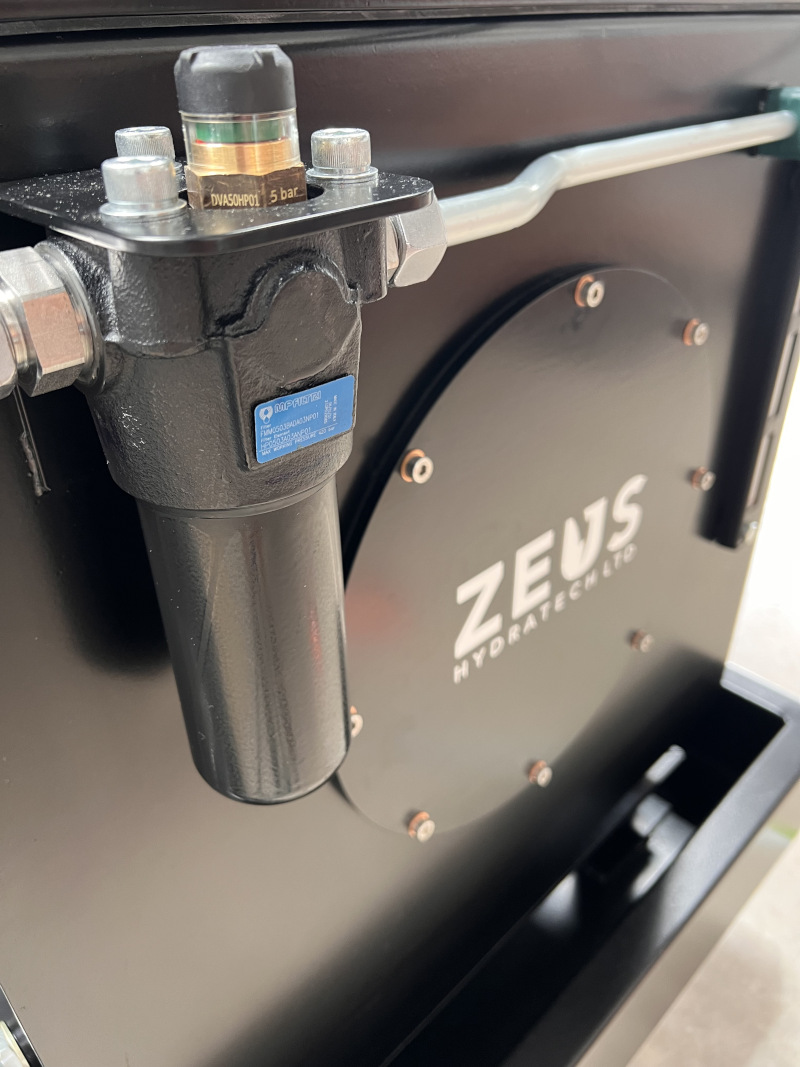
A filter is often incorporated into the reservoir to remove contaminants that may be present in the fluid. This helps to ensure that the fluid is clean and free from debris, which can damage the system's components. The type of filter and the micron rating of the filter will depend on the specific application and the fluid being used.
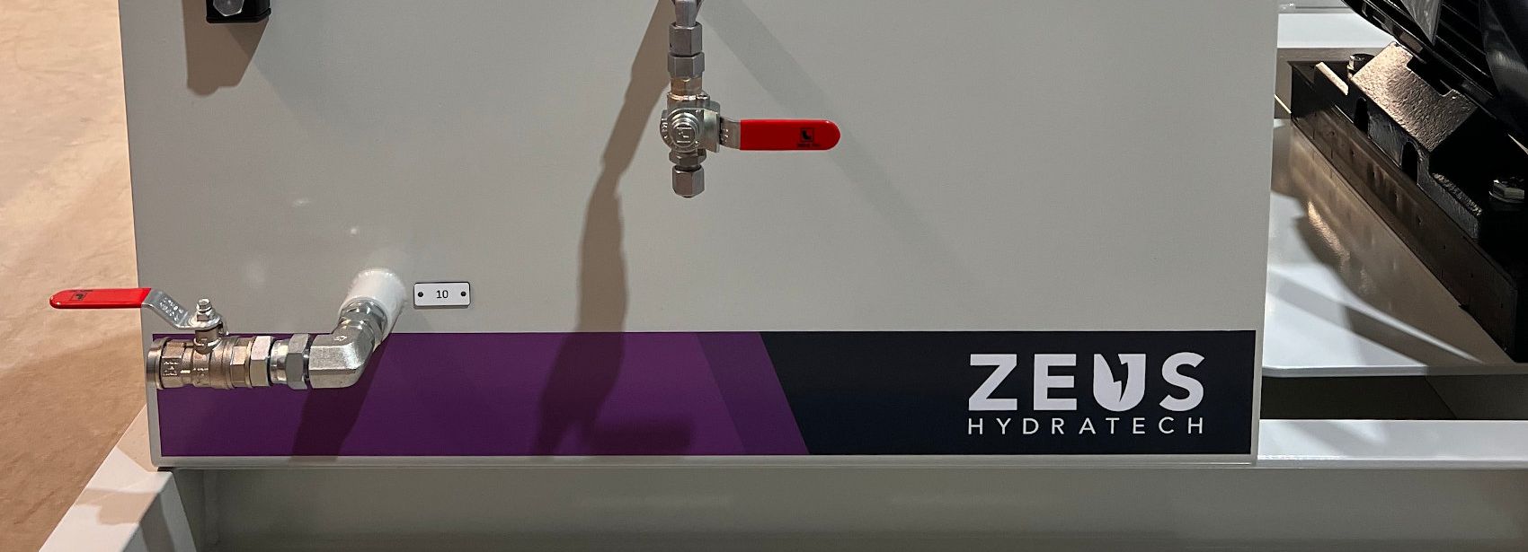
A drain valve is typically included to facilitate draining and cleaning of the reservoir. Also, the reservoir should have proper venting to allow air to enter and escape as the fluid level changes, preventing the formation of a vacuum or overpressure. This will also help to prevent any leakage or spillage of fluid. It is also important to ensure that the venting is properly protected to prevent contamination of the fluid.
When designing a drainage system for a hydraulic reservoir, an engineer should focus on the following elements:
Proper slope and grade - to ensure that water flows away from the reservoir and does not accumulate.
Adequate pipe size and length - to handle the expected flow rate and prevent blockages.
Use of appropriate materials - to withstand the environmental conditions and fluid being drained.
Properly placed and sized drainage outlets - to ensure that water is discharged in a safe and controlled manner.
Consideration of the potential for debris and sediment buildup in the drainage system and provision for regular maintenance.
Drainage systems are important for a hydraulic system because they prevent water from accumulating in and around the reservoir, which can cause corrosion and damage to the equipment. Drainage systems also help to remove debris and sediment that can accumulate in the reservoir and cause blockages in the system. Additionally, properly designed drainage systems can help to prevent flooding and protect the environment by safely discharging water away from the site.
Every pump will have a return line on it to account for the pump case leakage, it is important that these return lines return to the reservoir above the upper fluid level line so as not to create back pressure, which would result in damage to the system.
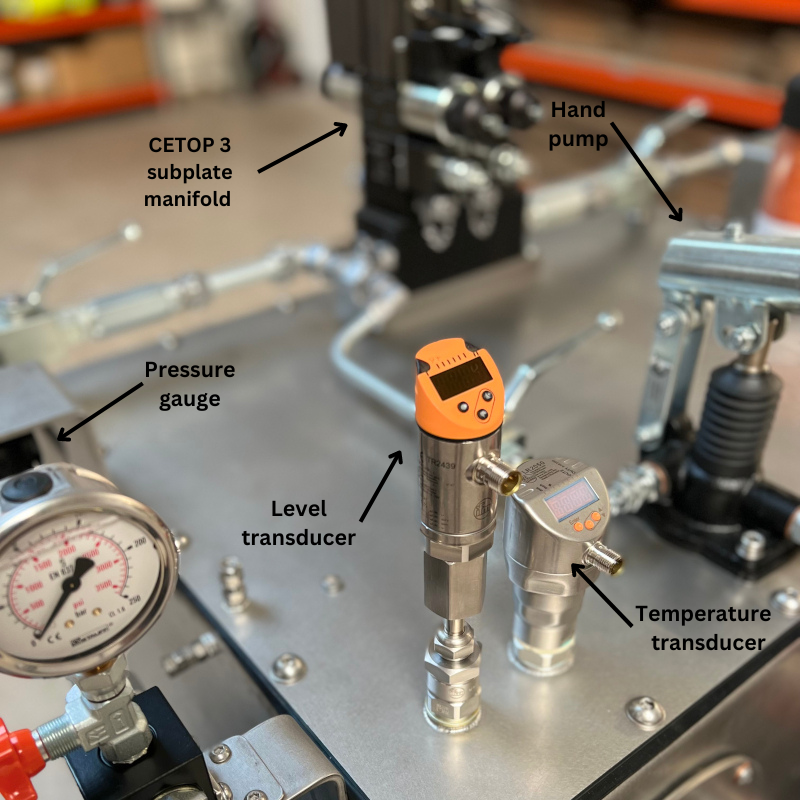
There are a number of ancillary pieces of equipment one can use to measure the performance of a system as well as ensure the system safety:
A visual level gauge can be used to determine the amount of fluid in a hydraulic system.
A level switch on a hydraulic reservoir is used to monitor the fluid level inside the reservoir. It works by sensing the presence of fluid at a certain point within the reservoir, typically using a float or reed switch. When the fluid level reaches the point where the level switch is located, it activates and sends a signal to the system's control system indicating that the fluid level is at a certain level. This information can be used to control the operation of the system, such as turning on or off a pump or activating an alarm if the fluid level is too low or too high.
A level transducer is a similar piece of kit that allows the user to set an infinite number of levels and configure the response of the system as the fluid level reaches each of those levels independently.


Vat Reg Number: 846644204 Company Registration Number: 5230249
© Copyright 2026 Zeus Hydratech | All Rights Reserved