Many hydraulic installations have a demand that includes operational periods of low pressure, high pressure, low flow and high flow. Input power does not reflect this varying consumption especially when variable pumps are running at low capacity. Innovative system design and component selection offer reduce consumed power and performance increase. Power saved can result in short payback times recovering cost and providing significant future power consumption savings. It is feasible to target a power reduction of 50%.
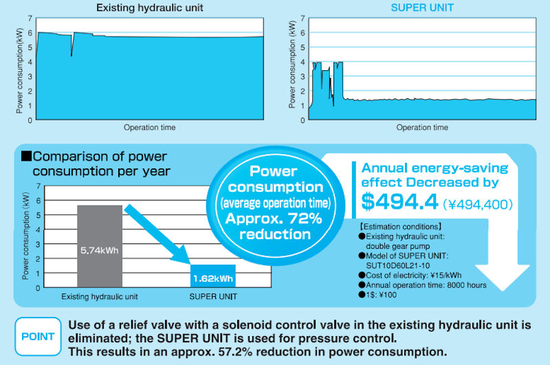
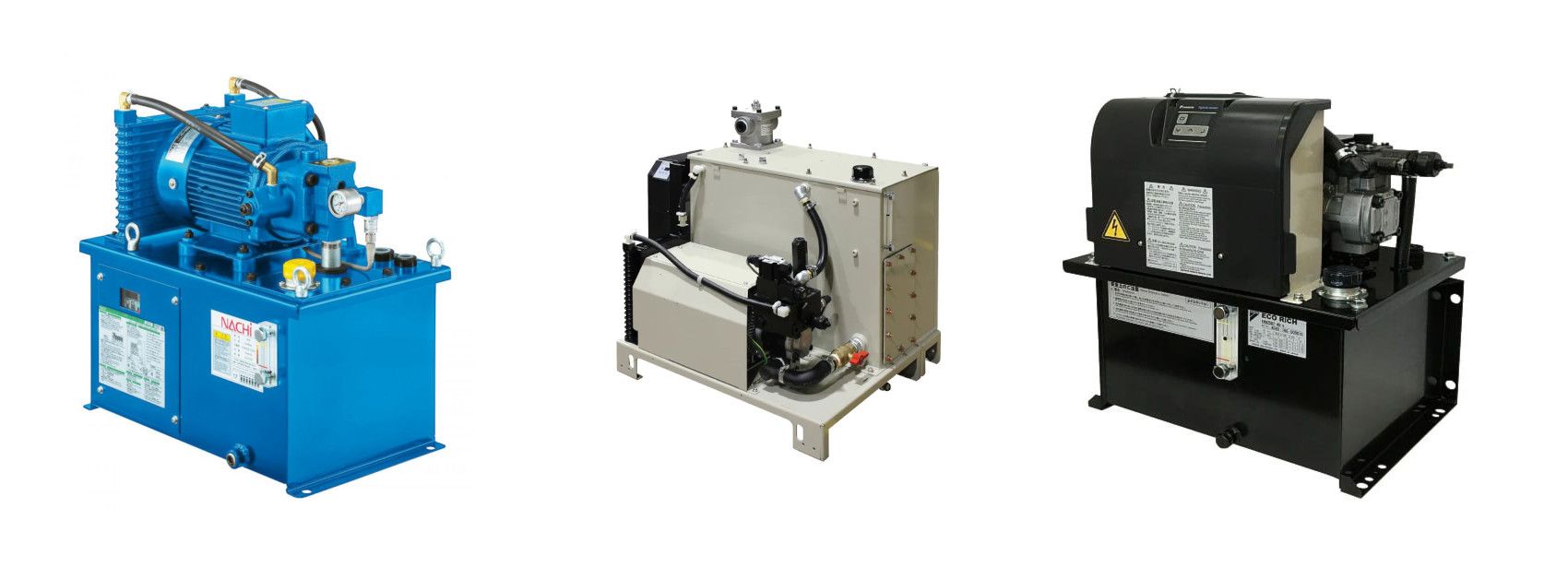
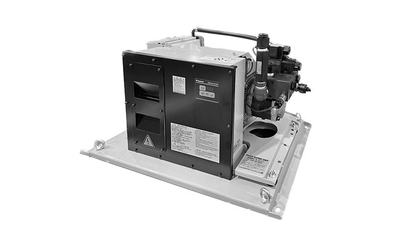
Above: A look at the savings in Power Consumption offered by using the Inverter Driven Daikin SUPER UNIT.
The efficiency of inverter driven induction motors shows that efficiency can vary by approximately 18% over the range motors available. The image below shows this variation across a range of motors across a desirable operating speed range.
The speed of the motor operates in a closed loop with feedback from pressure at the consumption point. This varies the speed of the pump to maintain desired pressure and reduce input power.
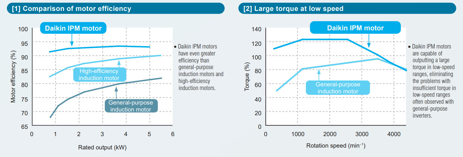
Above: A look at the efficiencies & torque of the Daikin IPM motor (Which is used in the Daikin EHU and SUT Hybrid units) compared to other motors.
Piston Pumps
In general the efficiency of variable capacity piston pumps is significantly reduced at lower flows. At flows of 50% of their full flow their efficiency can be reduced significantly to 60%.
Using a fixed capacity unit at varying speed can maintain a much higher pump efficiency over a wide speed (flow) range.
Piston pumps capable of 280/250 bar typically have 5 to 11 pistons which generate quite high levels of pump ripple especially at lower speeds. They frequently benefit from positive input port pressure (boost) and can require a continuous casing drain to remove excess internal leakage flow and heat.
Gear Pumps
External gear pumps are available for 280/250 bar have a greater number of teeth and in some cases special tooth shape which combine to reduced ripple.
Internal gear pumps generally offer reduced noise and higher pressure but do tend to have higher internal leakage and a higher minimum pressure.
External gear pumps can have lower internal leakage and lower minimum operating pressure and speed and generally do not require casing leakage drains and are capable of lower pressure and speed operation.
Pressure ripple is produced by the cyclic passage of the piston or tooth over the outlet port of the pump. More teeth result in the reduction of ripple amplitude and increases ripple frequency. Pump ripple amplitudes of 0.5 bar or less can be achieved.
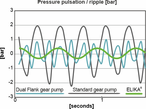
Above: A look the the pump ripple offered by a ELIKA helical gear pump compared to other options.
Pump Flow
Applications frequently have periods of low flow/high pressure and periods of high flow low/lower pressure. The use of a single constant speed pump to provide the high flow requires high power when operating at the high pressure.
The use of a double pump with a small and high flow capacity allows independent high and low pressure flows. In the high pressure stage the large capacity pump is unloaded to minimum pressure. It is important to have a pump capable of operating at minimum low pressure. External gear pumps are able to operate unloaded to 3 bar or less.
The minimum pressure state of each pump is achieved by unloading its relief valve behind a non return valve. These separate pump relief valves will be set at a high pressure than the system common relief valve to avoid interact
Reducing the consumed power will reduce the cooling requirement by increase efficiency and minimising wastage.
An external kidney loop with its own pump will cool and filter the bulk oil from the system reservoir.
The flow of this loop will be based on tank capacity to maintain the desired bulk oil temperature.
The dirtiest time for oil in the system is when new oil is replaced or system broken down for component change. New oil is not clean enough and system should be run for a period of time to achieve filtration levels required.
Fluid condition should be regularly monitored to overcome temperature cycling and water ingress can damaging fluids. In line filtration is necessary to protect components from system generated debris. These in line units all have cyclic flow and can be coarser. No filter should have a bypass but should have pressure drop detection (clogging switch).
The overall control would benefit from an intelligent digital system (computer). This would enable the most efficient power utilisation to be employed for the range of system requirements and not rely on operator selection. One or both pumps may be required combined with high or low pressure.
The maintenance of set pressure requires the motor speed control loop to be faster than the rate of change of demanded and to eliminate interaction.
The software programming the operational requirement, varying flow etc, can also generate a speed component to an inner loop of the pressure loop negating response interaction.


Vat Reg Number: 846644204 Company Registration Number: 5230249
© Copyright 2026 Zeus Hydratech | All Rights Reserved